


Project Data and Methodology
The data analyzed throughout the research project was sourced from six of the BIM2Build pilot projects. All of these projects fall under the DB-IG (Infrastructure Division). Beyond that, the projects vary significantly:
- Scope: Some projects involved the design of railway overpasses, while others focused on tunnels, stations, or technical station equipment.
- Scale: The selection includes relatively small construction projects as well as two large-scale projects.
- Status: Three of the projects have already been completed, while three others are currently under construction.
- Implementation: The projects also differ in the specific BIM Use Cases (AWFs) implemented.
Data Collection
Various types of data were collected for these projects:
- Contract Documents: (Employer’s Information Requirements, EIR; BIM Execution Plan, BEP; Bills of Quantities, BoQ; etc.)
- Design Phase Data: (Schematic and detailed design documentation)
- Models: (Discipline-specific models)
- Attribute Lists
- Project Documentation: (Daily construction logs, meeting minutes, etc.)
- Punch Lists: (Defect logs)
In addition, interviews were conducted with project leads, such as BIM managers, to gain a comprehensive overview of each project, gather feedback on their experiences, and clarify outstanding questions. For one project, an existing internal analysis was also provided for evaluation purposes.
Data Analysis Concept
To transform this extensive data into information—the second step of the DIKW pyramid (see methodology)—a data analysis concept was developed. The objective of this concept is to analyze the data as objectively as possible and to make highly diverse projects comparable. This data analysis concept is described and discussed in further detail by Noack et al. [1].
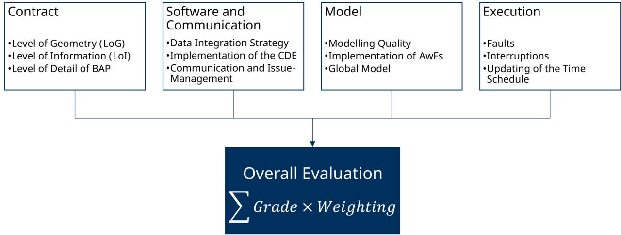
It is fundamentally based on 12 qualitative evaluation parameters, which should be assessed for each project whenever possible. The evaluation parameters are shown in Figure 2. The parameters are divided into the categories of Contract, Software and Communication, Model, and Execution. Using checklists, school grades (from 1 - very good, to 5 - unsatisfactory) are assigned for each evaluation parameter. These are then multiplied by the weightings from Table 1 and summed to produce category grades and an overall grade. The weightings were determined by BIM experts and agreed with the DB-IG. The grades are intended to enable an objective comparison of the projects with one another. At the same time, they help provide a rough overall impression of which aspects of the project and the test program in general went well and where there is still room for improvement.
| Category | Weighting Category | Evaluation Parameter | Global Weighting |
| Contract | 10 % | LoG | 2,5 % |
| LoI | 2,5 % | ||
| Level of Detail BAP | 5,0 % | ||
| Software and Communication | 35 % | Data Integration Strategy | 7,0 % |
| Implementation of the CDE | 14,0 % | ||
| Communication and Issue-ManagementManagement | 14,0 % | ||
| Model | 30 % | Modelling Quality | 15,0 % |
| Implementation of AwFs | 12,0 % | ||
| Global Model | 3,0 % | ||
| Execution | 25 % | Faults | 12,5 % |
| Interruptions | 6,3 % | ||
| Updating of the Time Schedule | 6,3 % | ||
| Sum | 100 % | 100 % |

Results of the Project Analysis
Using the data analysis concept, the individual projects were evaluated and compared with one another. To ensure confidentiality, the projects are discussed here only in anonymized form. Furthermore, no grades are published, nor are individual projects discussed in detail. Instead, for each category of evaluation criteria, the report identifies which aspects of the projects were successful and which require adjustments or improvements.
Contract
The contract documents, such as the AIA and the BAP, already contained numerous guidelines regarding the use of BIM, which supported the successful execution of the projects. For example, the BAP was generally formulated in great detail; roles, data transfer formats, deliverables, etc., were usually clearly defined, and the guidelines were often supported by examples. In addition, the BAP was updated multiple times in all projects to adapt it to changes as the project progressed, and some changes in the document were even highlighted in color for better tracking.
In the AIA, the level of geometry (LoG) was often defined in such a way that the contractor was to select it “appropriate to the intended use”. Although this requirement is certainly sufficient for contractors with BIM experience, it leaves a great deal of room for interpretation regarding how detailed the discipline models should ultimately be. A clearer definition here would provide greater certainty for all parties involved.
The example of the Level of Information (LoI) illustrates this very well. For the attributes of the specialized models, an attribution list was always provided that clearly defined for each AWF and for each LPH which attributes must be defined in the models and how they are to be populated. In most cases, the DB’s internal Semantic Object Model (SOM) was used for this purpose. However, since this model was not as advanced at the time of the pilot projects’ implementation planning as it is today, an additional attribute list was often specified within the project.
Software and Communication
An open big BIM approach was predominantly used for data exchange between project stakeholders and individual contractors. This means that all contractors worked with BIM and often used open exchange formats such as Industry Foundation Class (IFC) for the (specialized) models or the BIM Collaboration Format (BCF) for issue management. In some cases, proprietary formats were used to increase efficiency, meaning a closed big BIM approach was implemented.
The Common Data Environment (CDE) was usually the data exchange and communication platform in the projects. Extensive CDE functionalities were utilized to implement as many AWFs as possible with the platforms. This was mostly successful. However, the problem arose that some CDEs used for construction planning were not suitable for the execution phase. This was resolved by using a different CDE for execution. This approach was successful in the respective projects but is always associated with risks and additional effort.
Issue management was also model-based, utilizing BCFs that were created by the contractors individually as well as during planning and construction meetings, significantly accelerating the identification and resolution of problem areas in the models.
Modell
Modeling was carried out largely in accordance with modeling guidelines [2]. Consequently, the geometric detail of the models was appropriate for the requirements. When it came to assigning attributes, however, it often turned out that many attributes were not assigned at all or only partially, even though this was required by AIA and BAP and would also have been necessary for the individual AWFs.
Nevertheless, most of the AWFs were carried out without any problems. The linking of the models to bill of quantities (Leistungsverzeichnis, LV) positions was largely successful. The discipline-specific models were merged into a coordination model to conduct meetings and reviews, such as clash detection. During these meetings and reviews, design errors were successfully identified that, in conventional 2D design, would likely not have been noticed until on-site. It was still possible to adjust the design, and major defects were prevented.
The transitions to and from other project phases presented a significant challenge. Models from the design phase were often available but could not be reused due to their poor modeling quality. Remodeling for the execution planning phase was necessary. Furthermore, 2D plan derivation for review, as well as for construction, is still required by law and was also implemented. Both aspects were associated with significant additional costs and time expenditures, which are not present in a good and fully digital BIM planning process.
Execution
The actual execution of the completed projects was successful. There were no faults or interruptions that could have been prevented through better BIM planning. Interruptions did occur, for example, due to flooding, but such environmental factors are difficult to account for using BIM.
Such interruptions in the construction process can, however, be mitigated through model-based scheduling and construction progress monitoring, as this allows the entire construction schedule to be updated with minimal adjustments. This also helps increase the efficiency of planning and execution. In the pilot projects, however, the problem arose that linking the model to the construction schedule required a significant amount of effort that did not justify the benefits. Therefore, when planning AWFs, a cost-benefit analysis must always be conducted.
Literature
[1] T. Noack, P. Markert, B. Buuck, C. Barr, A.-H. Hamdan, C. Kang, S. Marx, Datenanalysekonzept für die Anwendung von BIM in der Bauausführung von Infrastrukturprojekten, Tagungsband 36 Forum Bauinformatik 24-26 Sept. 2025 Proc. 36th Forum Bauinformatik 2025 Hrsg. Von Baris Özcan Hristo Vassilev (2025) pages 179-186. doi.org/10.18154/RWTH-CONV-254907.
[2] Bundesministerium der Verteidigung (BMVg), Bundesministerium für Wohnen, Stadtentwicklung und Bauwesen (BMWSB), Bundesanstalt für Immobilienaufgaben (BImA), eds., BIM-Handbuch - Arbeitshilfe Erstellung von Modellierungsvorhaben, 2023. www.bimdeutschland.de/fileadmin/media/Downloads/Download-Liste/Hochbau/BIM_fu__r_Bundesbauten_AH_Modellierungsvorgaben.pdf.